
CDM-Type LTCC Chip Delay Line
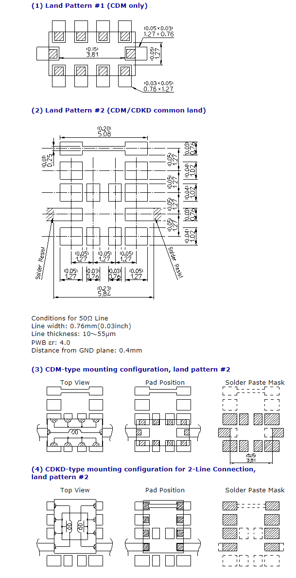
The CDM-type Delay Line is an LTCC (Low-Temperature, Co-fired Ceramic) chip Delay Line. By removing one (1) line from the CDKD-type differential Delay Line, we have been able to accommodate a very compact overall area of only 5mm x 2.5mm. In addition, we have described a CDM/CDKD common land pattern on which the CDM-type should be mounted for delay times within a 3ns delay range, and on which the CDKD-type should be mounted as a single-ended Delay Line, with the 2 differential lines connected in series (CDKD 2-line connection), for delay times over 3ns. We provide a 0.1~10ns delay range using a CDM/CDKD common land pattern. It is a RoHS-compliant component.
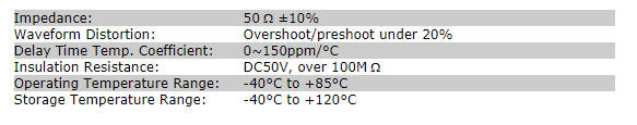
Care and Handling of LTCC Products PDF Catalog DownloadCommon Specifications
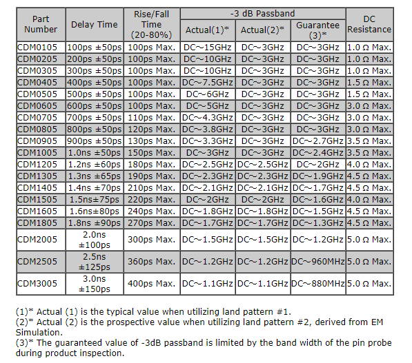
CDM Product Specifications
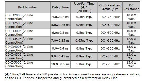
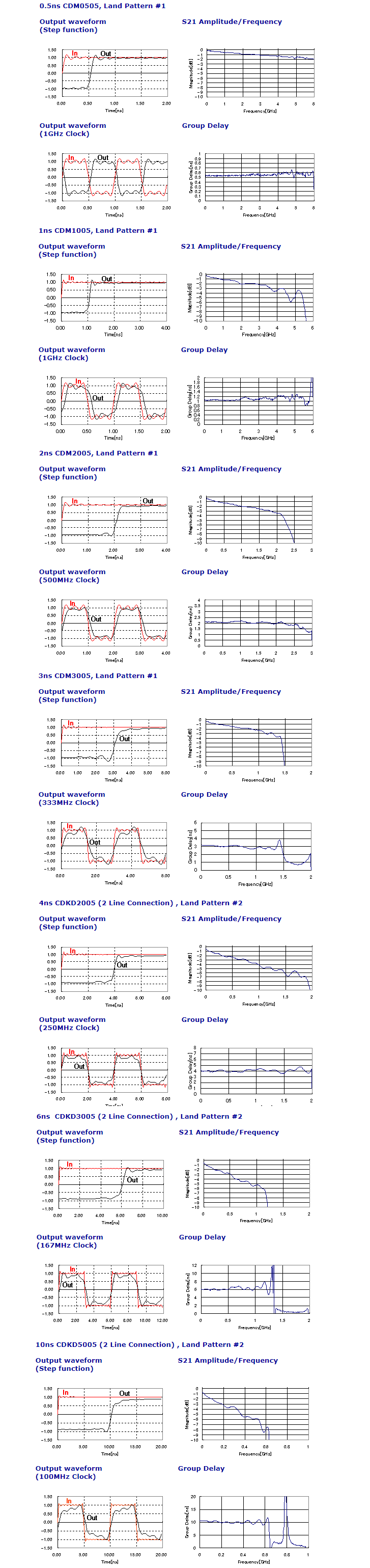
Characteristics of CDKD 2-Line Connection on land pattern #2 (For reference only.)
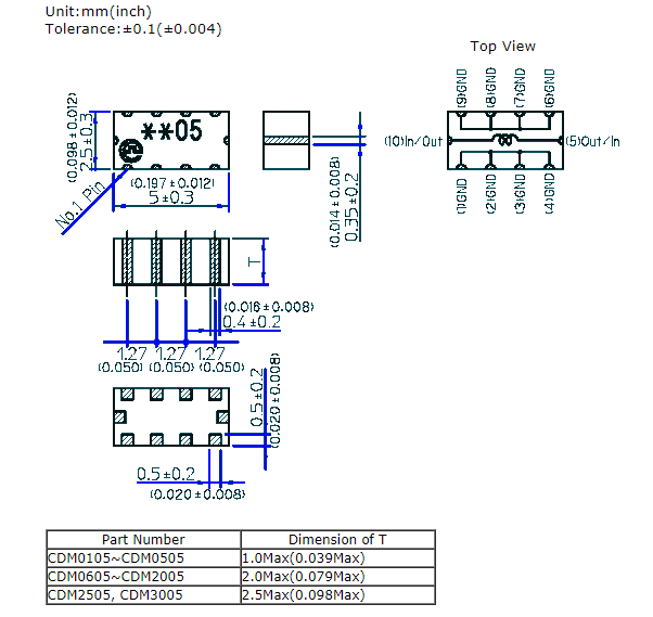
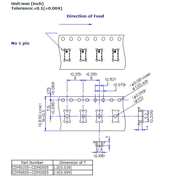
Package Dimensions & Pin Configuration
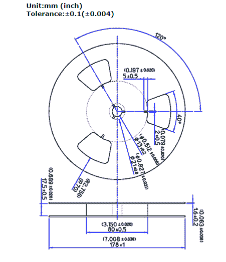
CDM-Type Tape and Reel specifications
Packaging of components can be in Tape and Reel for convenience of shipping and storage. The package is embossed with cover tape and contains 500pcs per reel, as shown below. The reel is marked with supplier name, part number, quantities, and lot number.
DIMENSIONS OF TAPE
DIMENSIONS OF REEL
Suggested Land Pattern
Reflow Soldering Conditions
Storage conditions are as per MSL1. These component families are not moisture-sensitive. Baking prior to reflow is not required.

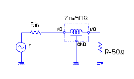
Typical Applications
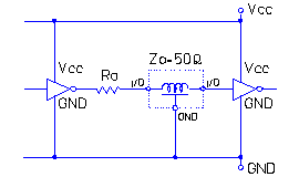
r: Signal Source Impedance
Rin: Input Adjustment Resistance
Zo: Characteristic Impedance of Internal
Elements (=Output Impedance)
Ro:Internal Adjustment Resistance (=Zo)
r+Rin=Zo=R
Ro should be adjusted to a value near Zo.
(1) Analog circuit
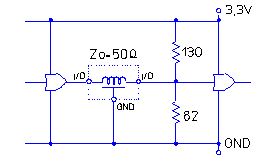
(2) PECL
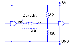
(3) LVPECL
(4) TTL/CMOS
Output Waveforms
RoHS Compliance Status
Initially developed only as a RoHS-compliant component.