
Absorbs and eliminates GHz-Band Multipath Reflection waves and noise emissions
Differential Signal Balancer/Common-mode Noise Absorber CDLD-Type R-Suffix Multipath Reflection Remover CDLD-Type E-Suffix
Features
- New, Non-magnetic Common-Mode filter utilizing delay line operating at 4G~28Gbps.
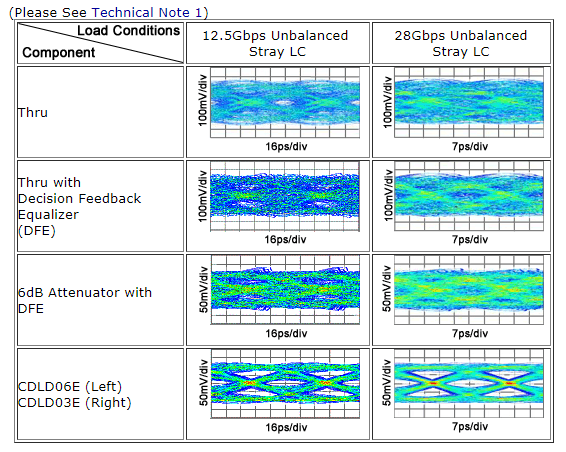
- Restoring Eye Patterns closed due to multipath reflection using the Passive internal CTLE (Continuous Time Linear Equalizer) version. (Please See Technical Note 1)
- Prior Removal and elimination of common-mode noise prevents noise transmission. (Please See Technical Note 2)
- Differential signal inter-phase skew and uneven Rise/Fall are automatically adjusted, correcting balance. (Please See Technical Note 3)
[Application Examples]
- Semi-conductor test device (Gbps) with common-mode noise transmission problems. (Please See Technical Note 4)
- Optical transmission system with an electrical/optical conversion board and high-speed networking device for EMI measure, eye pattern improvement.
This product is a 0805 size multi-layered ceramic chip-type LTCC part and is RoHS-compliant. S-parameter files (Touchstone format) and SPICE models can be provided for each component.
Care and Handling of LTCC Products PDF Catalog Download10Gbps Multipath Reflection Removal Example
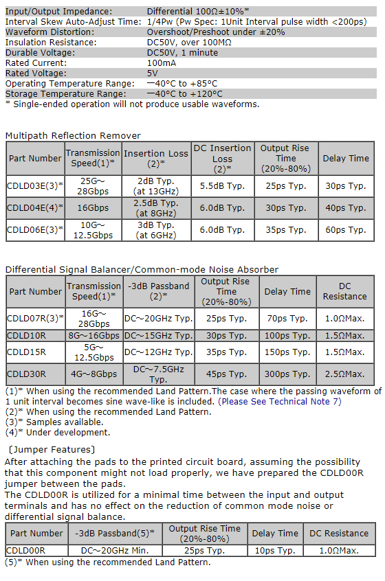
Common Specifications (provisional)
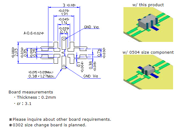
Package Dimensions & Pin Configuration(provisional)
- Unit:mm(inch)
- Tolerance:±0.2(±0.008)
- CDLD00R
・No Direction mark
・No connection between
- 2pin and 5pin
Suggested Land Pattern
Unit:mm(inch)
Tolerance:±0.1(±0.004)
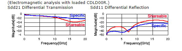
1. Specific Land Pattern
2. Available Common-mode Choke Coil (0504 size) with shareable Land Pattern
For differential balance improvement and common-mode noise elimination under 10Gbps, an inexpensive common-mode choke coil can even be used. However, considering unanticipated multipath reflection which could occur after production of the board, we recommend insertion of a land pattern which can also be used to mount this product. Below is an example of a land pattern which can also be used with an available 0504 size common-mode choke coil
3.Quality comparison of Specific Land Pattern and Shareable Land Pattern
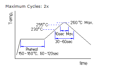
Suggested Reflow Soldering Conditions
J-STD-020C Pb-Free Standard
Storage conditions are as per MSL1. These component families are not moisture-sensitive. Baking prior to reflow is not required.
Typical Applications
(1) ECL
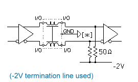
(2) PECL
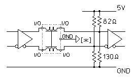
(3) LVPECL
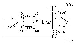
(4) LVDS
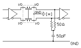
(5) CML
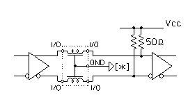
[*] Signal GND potential, such as a power supply GND or a Vcc line.Please be sure to connect the GND Termination. (Please See Notes)
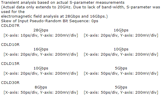
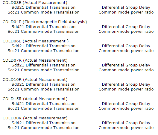
Characteristics Examples
Pulse response waveform
Frequency Characteristics
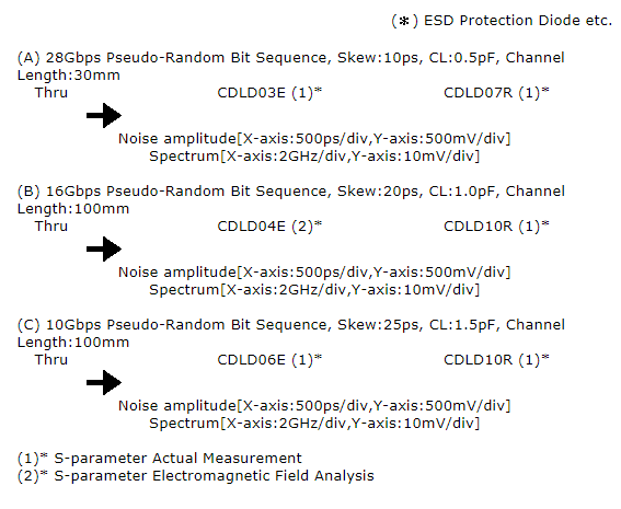
Technical Note 1: Example of Eye-Pattern Improvement/Multipath Reflection Removal
For transmission rates over 10Gbps, multipath reflection is generated from the capacitive load of IC’s ESD protection diode and pad which can cause deterioration of the eye pattern. Also, unintended unbalanced capacitive/inductive load should also be considered. Differential eye patterns connected with various capacitive/inductive loads are shown form a circuit simulation using the circuit shown below.
In spite of the capacitive/inductive load, it is possible to remove multipath reflection and improve a stable eye pattern with the CDLD type.

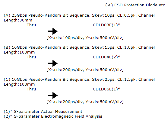
Technical Note 2: Example of Common-Mode Noise Elimination
For transmission speeds in excess of 10Gbps, even a minor skew will cause common-mode noise. Below is the circuit used to produce the common-mode noise wave form.
A CDLD-type is inserted directly after the IC, the GHz band common-mode noise is eliminated and transmission noise is prevented from returning to the original level.
Technical Note 3: Example of Differential Signal Balance Improvement
The wave form at the receiver will degrade due to skew or a connector GND discontinuity. The positive/negative differential signal wave forms of such a case are shown using the circuit below.
By using the CDLD with a passive internal CTLE, in addition to skew cancelation and improvement of the phase balance, it is also possible to cancel amplitude differences.
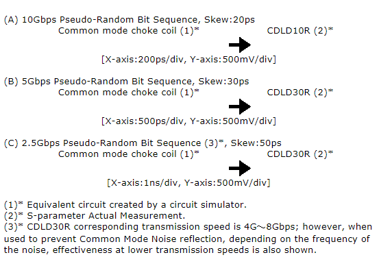
Technical Note4: Comparison of Common Mode Noise Input Reflection
For transmission speeds under 10Gbps, Common-mode Choke Coils are available; however, the reflection from the Common-mode Noise which is blocked by the Common-mode Choke Coil is quite large, the spike on the input wave form from the reflected Common-mode Noise will be superimposed. Using a comparator to compare the input and output wave forms, this superimposed noise can be quite detrimental. The positive/negative input wave forms of such a case are shown using the circuit below.
The CDLD-type’s ability to absorb the Common-mode Noise in the GHz band is quite high which prevents the superimposition of Common-mode Noise reflections on the input wave form.
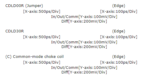
Technical Note5: Step Response Skew Improvement Example
Using a TDR Sampling Oscilloscope, we constructed and measured the test circuits shown below, positive/Negative(In(+)/In(-)/Out(+)/Out(-)), output common-mode noise(Comm)and the output differential signal(Diff)step response wave forms are shown. The CDLD-type, which contains a delay mechanism, delays the noise from the output waveform and avoids affecting the rise/fall edge.
Skew of signal source: 60ps
Technical Note 6: Frequency Characteristics of Common-Mode Impedance
For the CDLD-type and the ideal common-mode choke coil (hereafter, ideal CMC), the frequency characteristics of common-mode impedance are calculated with a circuit simulator and the difference is verified. The equivalent circuit and the main characteristics of the ideal CMC are shown in Fig. 1. As much as possible, the -3dB passband was made wideband.
Technical Note 7: CDLD Transmission Speed
The differential frequency characteristics (Sdd21) of a differential transmission line with a 30ps skew are shown in Fig. 1. In Fig. 1, a differential signal is intercepted to become a complete common mode signal at 16.7GHz because the 30ps skew makes a 180° phase shift at that frequency. Transmission of the differential signal forms an attenuation pole at 16.7GHz and the -3dB passband becomes DC to 8.3GHz.
RoHS Compliance Status
RoHS-compliant
Notes
Always connect the GND terminals. Using this product without connecting the GND could cause common mode noise rejection and delay line functions to deteriorate.Use of only one line will not yield a normal wave form and cannot be used.